
What Is a Logic Gate? 7 Types, Symbols, Truth Tables & Diagrams Explained
Introduction
Have you ever wondered how computers actually “think”? How does pressing a key on a keyboard translate into something your screen displays? The answer lies deep inside millions of tiny switches — and at the heart of all of it is something called a logic gate.
A logic gate is one of the most fundamental building blocks of all modern digital electronics. Whether it’s your phone, laptop, calculator, or even a traffic light controller — logic gates are quietly working behind the scenes, making decisions billions of times per second.
In this guide, we’re going to break everything down in simple, plain English. No confusing textbook language. By the end, you’ll understand what logic gates are, how they work, what the different types are, and how to read a logic diagram and truth table — even if you’ve never studied electronics before.
Let’s dive in.
What Is a Logic Gate? (Simple Definition)
A logic gate is a basic electronic device that takes one or more binary inputs (signals that are either ON or OFF, represented as 1 or 0) and produces a single output based on a specific logical rule.
Think of it like a decision-making machine. You give it some information — true or false — and it gives you back a result — also true or false.
In digital electronics, “true” is represented as 1 (voltage is high, switch is ON), and “false” is represented as 0 (voltage is low, switch is OFF). This is the foundation of the binary system — the language all computers speak.
Logic gates are physically made from transistors, but you don’t need to know about transistors to understand gates. All you need to know is: input goes in, output comes out, and the gate applies a rule.
Featured Snippet Answer: A logic gate is an electronic circuit that performs a logical operation on one or more binary inputs (0 or 1) and produces a single binary output. Logic gates are the basic building blocks of all digital circuits and computers. Common types include AND, OR, NOT, NAND, NOR, XOR, and XNOR gates.
How Do Logic Gates Work?
Logic gates work by evaluating electrical signals. Inside your computer or phone, everything operates on electricity — specifically, the presence or absence of voltage.
Here’s how it works in real life:
- When a wire carries high voltage (usually around 5V or 3.3V), it represents binary 1 (ON).
- When a wire carries low voltage (near 0V), it represents binary 0 (OFF).
A logic gate takes these voltage signals as inputs, processes them according to its built-in rule, and produces a voltage signal as output.
For example, an AND gate checks: “Are both inputs ON?” If yes, the output is ON (1). If even one input is OFF, the output is OFF (0).
This is similar to a real-world scenario: imagine two light switches in series (one after the other). Both switches must be ON for the light to turn on. That’s exactly how an AND gate behaves — it’s like two on-off switches connected in a row.
Logic gates are built from transistors — microscopic semiconductor switches. Modern computer chips contain billions of these transistors, all organized into logic gates, which then combine to form circuits that perform complex calculations.
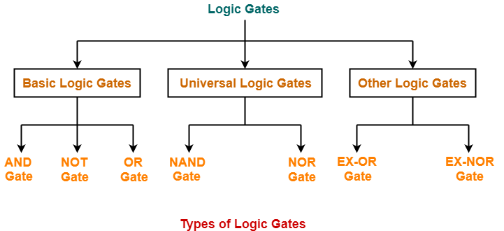
Types of Logic Gates (With Symbols and Truth Tables)
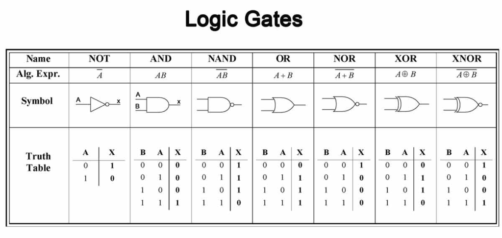
There are 7 main types of logic gates used in digital electronics. Each one has a unique symbol, a unique rule, and a truth table that shows all possible input/output combinations.
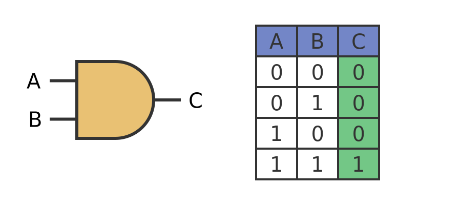
AND Gate
The AND gate outputs 1 only when all inputs are 1. If any input is 0, the output is 0.
AND Gate Truth Table:
| Input A | Input B | Output |
|---|---|---|
| 0 | 0 | 0 |
| 0 | 1 | 0 |
| 1 | 0 | 0 |
| 1 | 1 | 1 |
Logic Gate Symbol: A D-shaped symbol with a flat back.
Real-world analogy: A car that starts only when both the key is turned AND the seatbelt is fastened.
OR Gate
The OR gate outputs 1 when at least one input is 1. It only outputs 0 when both inputs are 0.
OR Gate Truth Table:
| Input A | Input B | Output |
|---|---|---|
| 0 | 0 | 0 |
| 0 | 1 | 1 |
| 1 | 0 | 1 |
| 1 | 1 | 1 |
Logic Gate Symbol: A curved, shield-like shape pointing to the right.
Real-world analogy: A room with two doors — you can enter if either door is open.
NOT Gate (Inverter)
The NOT gate has only one input and it simply flips it. 1 becomes 0, and 0 becomes 1. It’s also called an inverter.
NOT Gate Truth Table:
| Input A | Output |
|---|---|
| 0 | 1 |
| 1 | 0 |
Logic Gate Symbol: A triangle pointing right with a small circle (bubble) at the output.
Real-world analogy: A light that turns ON when the switch is OFF — the opposite of what you’d expect.
NAND Gate
The NAND gate is an AND gate followed by a NOT gate. It outputs 0 only when all inputs are 1 — the exact opposite of AND.
NAND Gate Truth Table:
| Input A | Input B | Output |
|---|---|---|
| 0 | 0 | 1 |
| 0 | 1 | 1 |
| 1 | 0 | 1 |
| 1 | 1 | 0 |
NAND gates are incredibly important in electronics — in fact, you can build any other type of logic gate using only NAND gates. This makes them a “universal gate.”
NOR Gate
The NOR gate is an OR gate followed by a NOT gate. It outputs 1 only when all inputs are 0.
NOR Gate Truth Table:
| Input A | Input B | Output |
|---|---|---|
| 0 | 0 | 1 |
| 0 | 1 | 0 |
| 1 | 0 | 0 |
| 1 | 1 | 0 |
Like NAND, the NOR gate is also a universal gate.
XOR Gate (Exclusive OR)
The XOR gate outputs 1 when inputs are different (one is 1 and the other is 0). If both inputs are the same, output is 0.
XOR Gate Truth Table:
| Input A | Input B | Output |
|---|---|---|
| 0 | 0 | 0 |
| 0 | 1 | 1 |
| 1 | 0 | 1 |
| 1 | 1 | 0 |
XOR gates are used heavily in arithmetic circuits — specifically, they form the core of a binary adder.
XNOR Gate (Exclusive NOR)
The XNOR gate is the opposite of XOR. It outputs 1 when inputs are the same, and 0 when they’re different. This is also related to the biconditional truth table in logic (A if and only if B).
XNOR Gate Truth Table:
| Input A | Input B | Output |
|---|---|---|
| 0 | 0 | 1 |
| 0 | 1 | 0 |
| 1 | 0 | 0 |
| 1 | 1 | 1 |
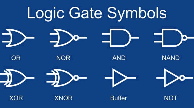
Logic Gate Symbols – How to Read Them
Every logic gate has a standard symbol used in logic diagrams (also called circuit schematic diagrams). These symbols are part of a universal visual language in digital electronics.
Here’s a quick reference:
| Gate | Symbol Shape Description | Boolean Notation |
|---|---|---|
| AND | D-shaped, flat left side | A · B or A AND B |
| OR | Curved arrow, convex back | A + B or A OR B |
| NOT | Triangle with a bubble at the tip | Ā or NOT A |
| NAND | AND shape with a bubble at the output | ̄(A · B) |
| NOR | OR shape with a bubble at the output | ̄(A + B) |
| XOR | OR shape with an extra curved line at the input | A ⊕ B |
| XNOR | XOR shape with a bubble at the output | ̄(A ⊕ B) |
When you see a small circle (bubble) on a gate symbol, it means inversion — the signal is flipped at that point.
Understanding these symbols is essential for reading any logic diagram or logical diagram in textbooks, datasheets, or engineering documents.
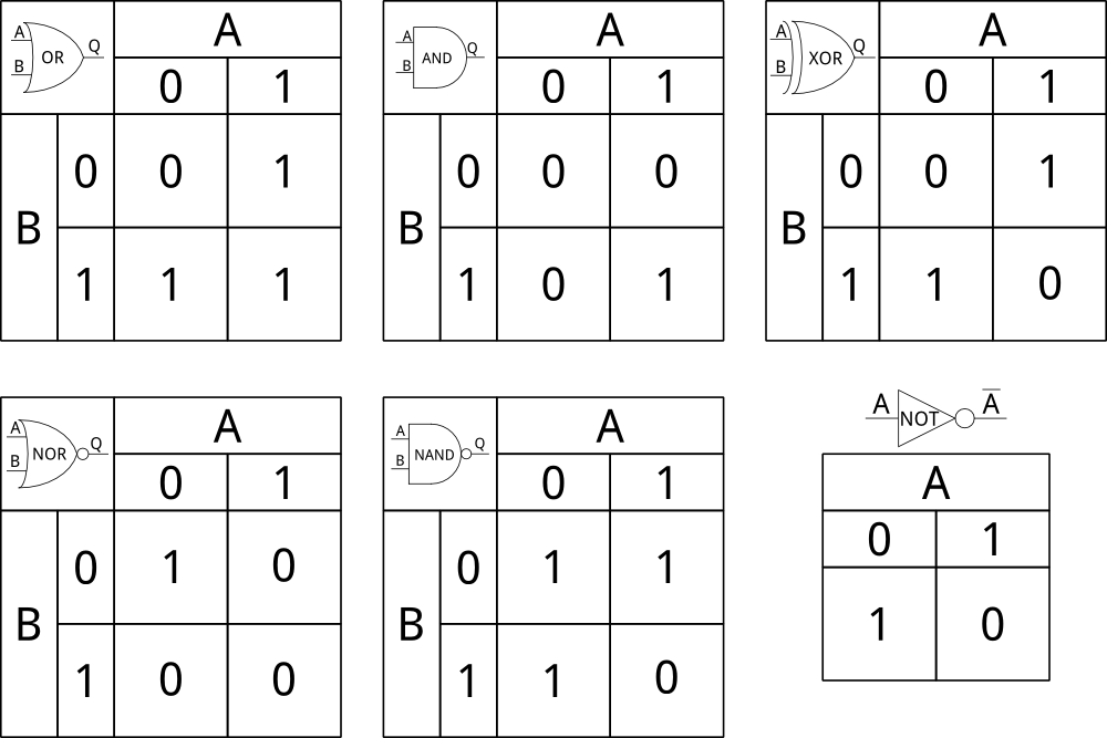
What Is a Truth Table in Logic Gates?
A truth table is a simple grid that shows every possible combination of inputs and the resulting output for a logic gate or digital circuit.
Think of it as a cheat sheet for a gate’s behavior. Instead of doing complex calculations, you just look up the inputs and see what comes out.
Here’s why truth tables matter:
- They help engineers verify that a circuit works correctly
- They’re used to design new circuits by working backwards from the desired output
- They’re essential for understanding logical gates before building anything physical
For example, if you’re designing an alarm system that should trigger only when Door A is open AND Motion Sensor B detects movement, you’d use an AND gate and verify its behavior with a truth table before wiring anything.
Truth tables also connect directly to Boolean algebra — the mathematics of logic that underpins all of digital computing.
Logic Gate Diagrams – How to Build and Read Them
A logic diagram (also called a logical diagram) is a visual representation of a digital circuit using gate symbols, input lines, and output lines connected together.
Here’s how to read one:
- Start from the left — inputs come from the left side of the diagram.
- Follow the wires — lines connect gates together.
- Identify each gate — look at the shape to know the gate type.
- Trace to the output — the final result comes out on the right.
Example: A Simple 2-Gate Logic Diagram
Imagine you have inputs A, B, and C. You want the output to be 1 only when (A AND B) OR C is true.
Here’s how you’d build it:
- Connect A and B into an AND gate → produces intermediate result (A·B)
- Connect that result and C into an OR gate → final output
This is a simple but real pattern you’d find in digital circuits. When you string multiple gates together like this, you create what’s called a combinational logic circuit — the backbone of all digital electronics, from calculators to CPUs.
Real-World Applications of Logic Gates
You might be thinking — “Okay, this is interesting, but where do I actually see logic gates in real life?” The answer is: everywhere.
Here are some everyday examples:
- Computers and smartphones — Every processor contains billions of logic gates performing calculations and running apps.
- Digital calculators — XOR and AND gates work together in adder circuits to perform basic arithmetic.
- Security systems — AND gates check multiple conditions (e.g., correct PIN AND valid fingerprint) before granting access.
- Traffic lights — NOR and NOT gates help manage light sequencing logic.
- Medical devices — Logic gates process sensor signals in devices like heart rate monitors.
- Automotive electronics — AND gates appear in safety systems (like airbag deployment logic).
Even something as simple as a 4-pin relay wiring diagram uses basic logic principles — the relay itself acts like a switch that can be controlled by a gate’s output.
Understanding logic gates isn’t just for computer scientists. Engineers, hobbyists, and makers use them every day to build smarter circuits.

Logic Gates vs. Binary Switches – What’s the Difference?
People sometimes confuse logic gates with simple binary switches. While they’re related, they’re not the same thing.
A binary switch is just an on/off switch — it either passes a signal or doesn’t. Think of a light switch. It has no logic; it just opens or closes a circuit.
A logic gate, on the other hand, evaluates a rule. It takes inputs, processes them, and decides an output based on logic (AND, OR, NOT, etc.). Multiple switches can be combined to simulate a logic gate, but a gate itself is a pre-built, reliable electronic component.
In digital circuits, logic gates replace the need for physical switches. They’re faster, smaller, more reliable, and can be combined in the millions on a single tiny chip.
Conclusion
Logic gates might sound like advanced computer science, but as you’ve seen, the core idea is beautifully simple: take some inputs, apply a rule, get an output. From the basic AND gate to the versatile NAND gate, each one plays a specific role in helping computers and digital devices make decisions.
Whether you’re a student just starting out with digital electronics, a hobbyist building your first circuit, or just someone curious about how technology works — understanding logic gates gives you a genuine peek under the hood of every digital device you use.
Start by memorizing the 7 gate types, their symbols, and their truth tables. Then try drawing a few logic diagrams on paper. Before long, you’ll be seeing logic gates everywhere — because they really are everywhere.
Frequently Asked Questions (FAQ Schema)
Q1: What is a logic gate in simple words?
A logic gate is an electronic circuit that takes binary inputs (0s and 1s) and produces a binary output based on a specific logical rule. It’s the basic decision-making unit in all digital electronics.
Q2: What are the 7 types of logic gates?
The 7 main types of logic gates are: AND, OR, NOT (Inverter), NAND, NOR, XOR, and XNOR. Each has a unique symbol, truth table, and behavior.
Q3: What is a truth table in logic gates?
A truth table is a chart that lists all possible combinations of input values and shows the resulting output for a logic gate or circuit. It’s used to understand and verify how a gate behaves.
Q4: What is a NAND gate and why is it special?
A NAND gate is a combination of an AND gate and a NOT gate. It outputs 0 only when all inputs are 1. It’s called a “universal gate” because any other logic gate can be built using only NAND gates.
Q5: Where are logic gates used in real life?
Logic gates are used in computers, smartphones, calculators, security systems, medical devices, traffic controllers, and virtually all digital electronics. They are the fundamental building blocks of modern technology.